 ENG
ENG


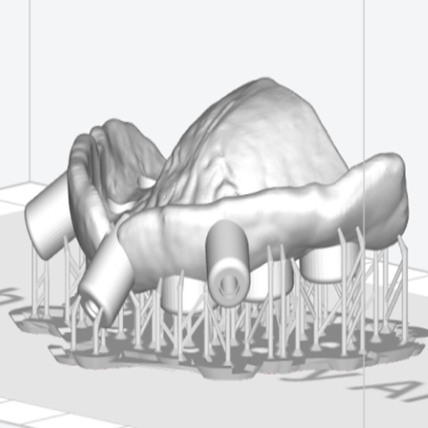
Table of Contents
The development of osseointegration has rapidly led to the use of dental implants in recent years. Dental implants have become a treatment option for the replacement of lost teeth. An accurate implant guide plate is important for the success of implant surgery. How to make an accurate implant guide plate? This article will discuss the topic of how to print a surgical guide.
What is the digital implant surgical guide plate?
CBCT data and intraoral scan data (or plaster model data) are used to reconstruct the three-dimensional of patients’ oral and face. Taking all factors into consideration, such as patients’ lost teeth, bone situation, and critical anatomical marks. Technicians design the most suitable implant surgical guide plate to allow a dentist to place an implant body in a very specific, pre-planned location in order to give an ideal depth, angle, and size of the implant to fit the space(Fig1).
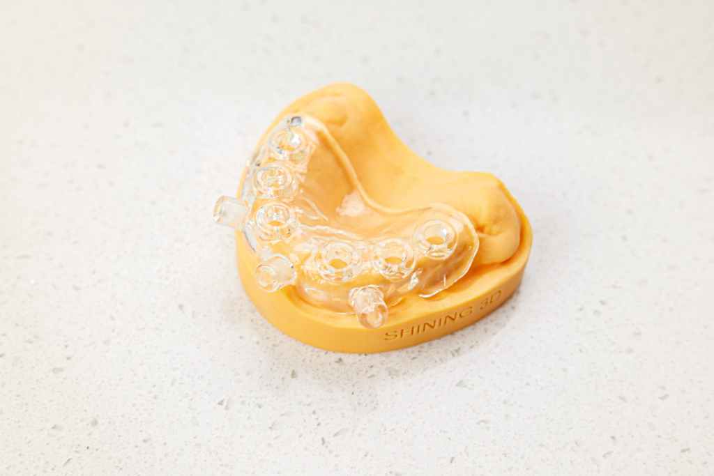
Fig1: The surgical guide plate
Why do we need an implant surgical guide plate?
There are several advantages of implant surgical guide plates. It reflects the preoperative setting site accurately to achieve restoration-oriented implant treatment. It guides the process of the implant surgery and reduces the operation time. The non-flap technique accelerates mucosal healing with less bone loss and brings less postoperative discomfort.
Why are implant surgery guides inaccurate?
Data error, design or printing deviation and operation are three main reasons for the failure of implant operation. Data error includes inaccurate CBCT, like oral movement artefacts, intraoral scan data deviation or poor alignment. Misoperation is something like the placement of the guide plate in the mouth is not accurate, the gap value between the guide ring and drill needle is not appropriate, etc. The design or printing deviation is whether the design of the guide plate is reasonable, whether the process of guide plate printing is controllable, whether the assembly of the guide ring and guide plate is correct, etc.
How to print an accurate surgical guide plate?
1. The adjustment of the printer
A 3D printer can make the implant guide plate with photosensitive resin. Before use, in the equipment debugging stage, the accuracy and consistency of printing are ensured by adjusting the two parameters of scale compensation and contour compensation (Fig 2). Besides, set appropriate guide plate parameters, such as thickness, tooth or model offset, amount of concave retention, and compensation from the guide ring.
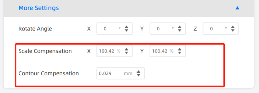
Fig 2: The interface you can adjust the scale compensation and contour compensation
2. The layout and design before printing
3. The printing thickness and step pattern on the side walls
If the guide hole is not vertical while printing, there will be steps on the side walls which result in resistance when the guide ring is placed. The thicker the layer, the faster the printing speed, and the more obvious the step pattern on the side walls (Fig 3). To avoid these step patterns, it is recommended to lay the component with its guide hole vertically to the printing platform (Fig 4).
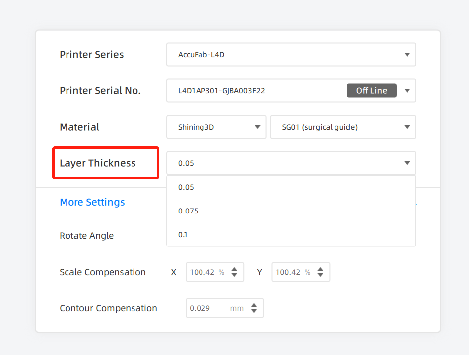
Fig 3: The interface to adjust the layer thickness before printing
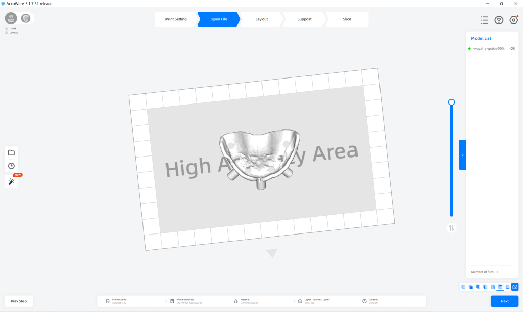
Fig 4: Layout the component with its guide hole vertical to the platform
4. The support adjustment
Remove the support inside the guide hole. If there are supports inside the guide hole, the refined grinding will lead to the deviation of the guide plate. The top support is spherical (Fig 5), so it is easier for us to remove the support after printing.
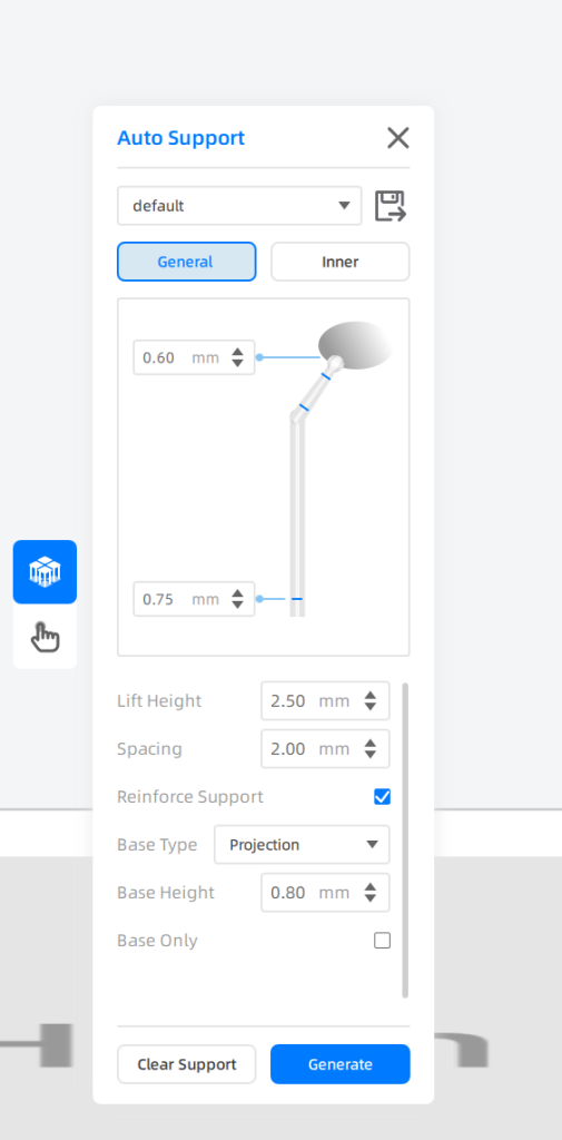
Fig 5: The spherical top support
The base is shaped like a boat, so we can remove the parts using a knife easily(Fig 6). Adjust the diameter of the spherical and the support rod carefully. An experienced user can adjust the support with perfect parameters that are strong enough to hold the parts and suitable to remove at the same time(Fig 7).
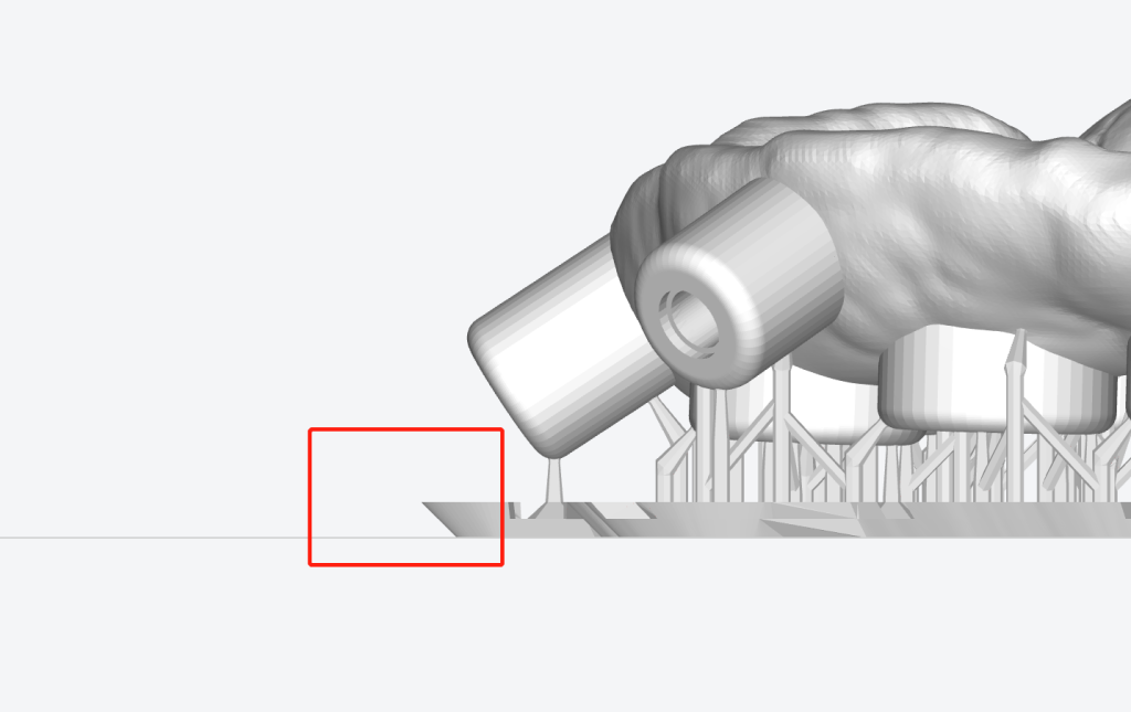
Fig 6: The base is shaped like a boat for easier removal.
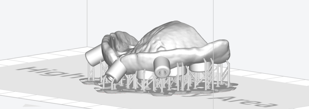
Fig 7: Generate support
5. The resin for printing a surgical guide plate
Different photosensitive materials have different clinical applications in the dental industry. SHINING 3D has several different kinds of photosensitive resins(Fig 8).
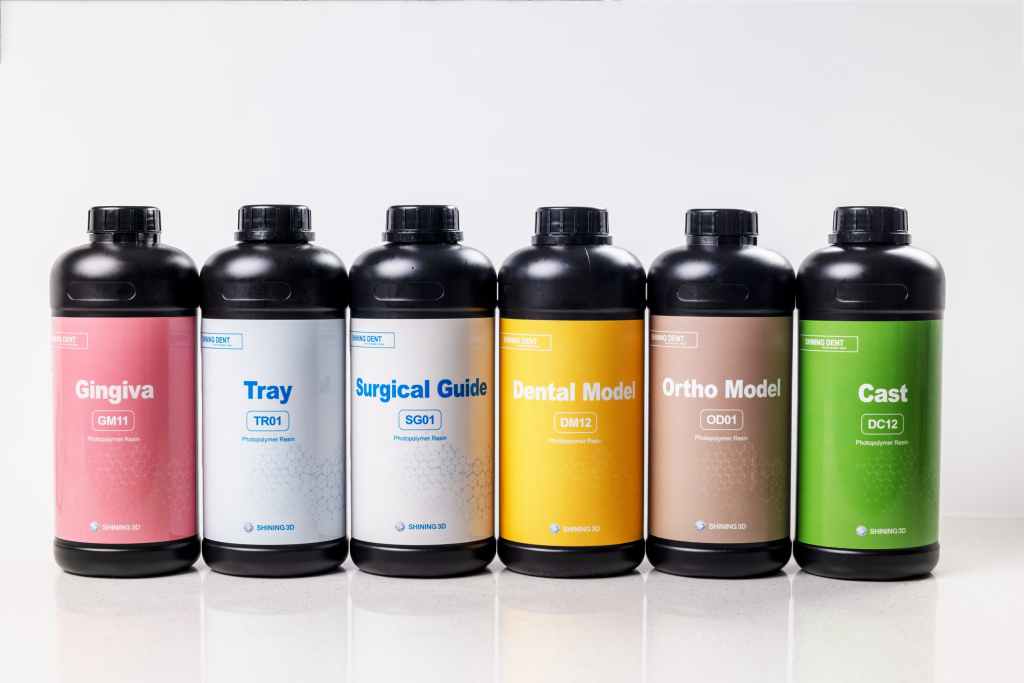
Fig 8: Different kinds of resins provided by Shining3D.
To print the surgical guide, we recommended photosensitive resin: SG01(Fig 9), which had been tested and verified with biocompatibility. To minimize the deviation of the printing process, the requirement of temperature is between 20℃ and 30℃, the humidity is around 25%. In this condition, the swelling of the liquid is small, thus ensuring higher accuracy of the printing components.
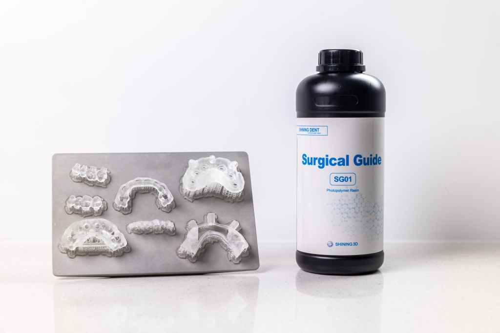
Fig 9: The Surgical Guide resin SG01 provided by SHINING 3D.
6. The post-processing
Cleaning the components with IPA ≥90% or ethanol ≥90% until the surface does not feel sticky, if necessary, use ultrasonic oscillating equipment or interdental brush. After cleaning, dry the components with compressed air. Assemble the guide ring with a guide plate before curing in the FabCure 2 (Fig 10), then post-curing for a recommended time.
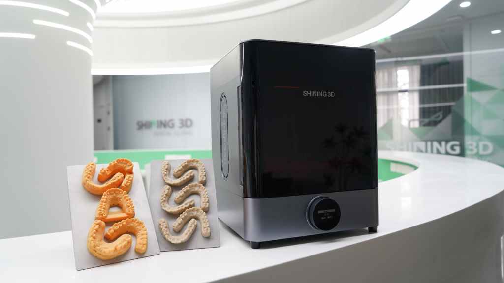
Fig 10: Fabcure 2, a device for post-curing light
To recap, these are strategies for printing a surgical guide plate.
For surgical guide plates without guide ring
- Ensure the guide holes are vertical. In this way, the inner wall is smooth, and there is no resistance when the drill needle enters.
- No support on the fitting surface.
- Fully exposed observation and cooling windows, observation window help dentists check whether the guide plate is placed on the dental arch completely. The cooling window is where the cool water is injected to avoid bone burn during operation.
For surgical guide plate with a guide ring
- Ensure the guide holes are vertical and have a common path of insertion.
- Check carefully to make sure there is no support around the guide ring and bonding hole.
- Expose observation and cooling windows.
- Enough support at the lowest point of the components.